Resurrection: 1965 BSA C15 (SS80)
I recently finished rebuilding and restoring my original 1968 Triumph TR6R that I purchased locally. It was a long project but it's now back on the road where it belongs.
Since I always like to stay busy I have found a new project to work on which I happened to have here at the shop tucked away in storage.
This little BSA project is 1965 C15 (SS80). The BSA C15 was a 250cc motorcycle suited for beginner motorcycle riders and also blue collar workers alike.
Last year (2017) I wrote a brief blog post on this C15; click here to read that blog post.
My first British motorcycle I rode was also 1965 BSA C15... and it happens to be this exact bike.
If you have any questions feel free to drop a comment in the comment section below and we will answer at our earliest convenience.
I will be updating this post when necessary.
Let's dive right in...
Sealants & Lubricants
One of the "secrets" when putting an engine together lies within the preparation and quality sealants and lubricants used. Below I will go over some of the sealants and lube types I used on this 1965 BSA C15 build.
I stock some of the lubes and sealant that I used on my build here on my site, you can click on some of the products if you see a link to them.
| Sealant | Lubricant | Application | Brand |
| Copper Spray | Head Gasket | Permatex | |
| Silicone (1184) | Gear Box Covers | Three-Bond | |
| Assembly Lube | Various Engine Components | Sta-Lube | |
| Gasket Dressing | Paper Gaskets | Gasgacinch | |
| Red High Temp RTV | Exhaust Header | Permatex | |
| 10w-30 | Break-In Engine Oil | Maxima | |
| 20w-50 (VR1) | Running Oil | Valvoline | |
| 80w-90 | Gear Box | Lucas Oil | |
| 5w-20 | Primary Chain Case | O'Rielly | |
| Grey RTV Silicone | Gear Box Sprocket Splines | Permatex | |
| P90 | Rubber Components (misc) |
The Resurrection
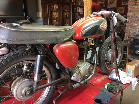
The BSA C15 (SS80) up on the bench exactly in the same condition how I left if about 8 years ago.
It had been neglected by the previous owner and was put into storage by us due to other more important projects around the shop.
Now that it's up on the bench it's time to do a check and thorough cleaning to see the true condition of the motorcycle.

Before I touched or attempted to remove any other components I wanted to work on I decided to remove the top end to see the condition of the piston and barrel.
Checking the top end will give me an idea of what condition the engine is.
I also wanted to check the crank rod for "up and down" play.
As you tell by the photo above, this motorcycle was dirty and neglected but when it ran, it ran strong - a real blast down the back dirt roads.
The top end on the BSA C15 models literally take about 15 min to remove including removing the Petrol tank from the frame.

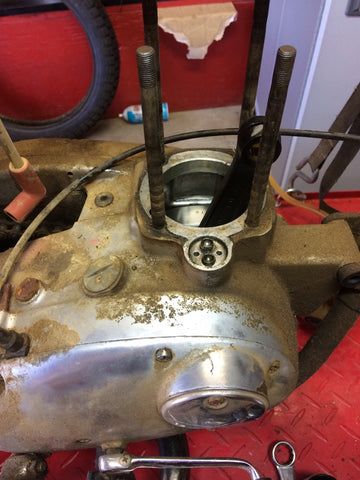
Cylinder head is off and to my surprise the piston is on +.060".
I'm surprised as I thought this 250 was at least on +.020". I could only assume at some point perhaps the piston seized or this 250 has some serious miles racked on it.
*I used 2 picks to plug up the push rod tube oil holes to stop and debris going into the crankcase.
Cylinder barrel is off and now we check the rod for any type of wear.
Rod has a minimal amount of "up and down" play. I'll take my chances and leave the bottom end.
If I have to rebuild it later on that is fine. I'm in no rush to rebuild the engine and I'm sure I can get many miles out of it.
The times we had it running the engine was very strong - no funny noises.

Since the top end is completely dissembled now it is time to clean all parts and inspect.
The cylinder head appears to be in good shape - no cracks or any broken fins.
Once it's all clean I can dig in to find any type of issues.

I will use an ultrasonic cleaner to thoroughly clean the cylinder head, rocker box and cylinder barrel.
FYI the ultrasonic cleaner I use was purchased off eBay. You can adjust the temp up to 80 Cecilia with a 30 minutes timer. I use half water and pine sol for the best results.

As far as I'm concerned the cylinder head was in for a major over haul.
Both inlet and exhaust valve guides where the original cast iron types and where heavily worn.
The exhaust valve guide was spinning in the head (not good).
I replaced both valve guides with new Kibblewhite valve guides. The new guides are solid bronze (C630) and where +.002" sizes.
I had to ream each guide using a Kibblewhite reamer. The valves in this head where original and where the right diameter and length.
Not shown - after I reamed the guides I used a Kibblewhite ball hone to finish the size. I also used a Newsy cutter to cut the seats using the new guides as a pilot.
Stem to guide clearance
- Exhaust approx .003"
- Inlet approx .002"
Some would run the guides tighter and some would run them looser. These specs should be fine.
*Kibblewhite Triumph 500 (unit) guides are the same fit and design as the BSA C15 and B40 models. This original guides had a circlip fitted to the guide. You can do away with the clips with new Kibblewhite guides.
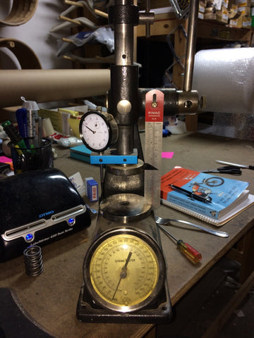
The last thing I wanted to check before finishing the head was the valve spring using my vintage 1980's Rimac valve spring tester.
The valve springs that where removed where not original, although they did have the correct progressively wound design the seat pressure was to high.
I found a pair of NOS outer valve springs off of eBay. The new valve springs today for the C15 and B40 models are junk which is why I don't use them or sell them.
The new "UK Made" springs @1 5/16" installed height measured in at @85lbs while the NOS springs where @70lbs.
The new "UK Made" springs at max Lift (.325) where @180lbs while the NOS springs at max lift was @164"lbs.
Using the correct springs will make your camshaft and valve train last longer!
*The only specs on the valve springs are the installed height, valve specs and spring dimensions. BSA Service Sheet gives an installed figure of 1 5/16". There are no other specs on any of the valve components.

The cylinder barrel was bored at some point and showed very little signs of wear. The piston looks to be new.
I wouldn't be surprised if the barrel and piston had less than a 1,000 miles on it.
Not shown - I checked the barrel for "out of round" using my bore gauge and I got about 0005"-.001" throughout the bore - works for me.
I installed new Hastings +.060" rings. All where cast rings except the top, the top was chrome.
Everything was looking good so I did a quick hone using a 220 glaze buster and installed the piston and rings DRY only lubing the wrist pin.
*I sand blasted the barrel then painted the barrel using a high gloss VHT engine enamel paint.
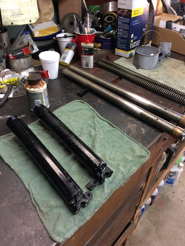
The C15 forks are about the easiest set of forks that I have ever rebuilt.
One thing I can't stand is leaky forks. It bothers me so I had to take them apart just to make sure they where serviceable.
The forks that came on this C15 where NOS that where installed about 10 years ago by my pops.
Since then the seals have blown and every price of desert dirt, trash, and debris worked its way into the seal holders damaging the seals.

Each fork leg uses X2 fork seals. Strange right?
The fork seal holders are pressed together and removing them to change the seals is some what of a pain.
Once the fork seal holders are apart you can install the new seal stacking 2 of the same seals on top of each other then pressing the seal holders back together.
The design works but clearly BSA was trying to keep costs down by using this method of securing the fork seals.
*You have to use a special service tool to remove the fork seal holders from the leg. You can use the same tool to install them back onto the leg. Since the forks relies on oil thickness to dampen them, I used 20W fork oil since I'm light person.

Before installing the fork sliders in the triple trees I thought now would be a good time to work on the electrical in areas where it mattered such as the headlight.
The headlight nacelle was purchased over 30 years ago. I installed the nacelle with all other parts for the headlight that we had been saving for.
New parts where a Lucas headlight, Lucas 88SA lighting switch, NOS Smiths speedo, and a new Lucas 8-0-8 ammeter.

Here is the front headlight assembly all sorted out.
I also mounted new European style 7/8" bars along with new levers, grips and a Wipac Ducon switch.

The next difficult part was the battery compartment. It was dirty, messy and everything was wrong..
The battery I replaced with a new 6V unit manufactured by Yuasa. (Yes I'm keeping the bike 6v)
I thoroughly cleaned the battery compartment and also fixing a missing tab that connects the battery box to the inner tool box.
Vibration must have killed the bracket.

Its amazing what a little cleaning can do. When there is a of dust and grime I always use simple green on the frame and polish away.
The new battery is a perfect fit. I got it filled locally for $10.
Not shown - I purchased a "period correct" Lucas horn from England. It is the smaller 8H horn which is correct for this bike. I cleaned up the original Lucas coil and installed a new Lucas 49072 rectifier. A used (working) Lucas 88SA ignition switch was found here and installed - I had to replace the key.

While waiting for parts from all corners of the world I started to remove the primary and components.
The stator was trash - missing all 3 wires and the rotor was in good shape.
I removed all clutch parts and dumped them in my ultrasonic cleaner for about 5 hours to remove any type of oil and debris.

I had a very hard time removing the crankshaft front sprocket. I purchased a $10 pulled from O'Rielly and it quickly bent the arms.
I purchased another puller from PepBoys (as shown) and it did the trick.
Not shown - I replaced the oil seal that sits behind the sprocket as shown. The seal had been replaced before but now is a good time to renew t since the clutch is apart.
*If is very risky to replace and change the crankcase oil seal as lies very close to the crank bearing. Take caution when removing and replacing.

While the top end and clutch is completely dissembled now is a great time to start working on removing the inner and outer timing side covers.
The reason for the removal of the gear box was because the main shaft bearing was worn.
You could literally lift the mainshaft and toss it from side to side - it was that bad!
*This set up as shown is new for 1965. The mainshaft features a ball bearing where as pre-1965 where fitted with a mainshaft bushing. The 1965 (and on) gear boxes are one of the strongest that where fitted to the C15 models.

With the gear box apart I took the liberty to replace the 1-piece bronze bushing with a set of NOS BSA later 2-piece split bushings.
The bushing that was removed from the high gear was beyond worn. I'm surprised it held oil as good as it did!
*I used a 20 ton press to remove the old bushing and to install the new bushings. Using a 2-piece bushing allows a much easier installation process. You must measure your old bushings protrusion and install the new bushings to the same specs.

I did some sanding on the inner timing cover to remove most of the gouges, nicks and scratches.
I start coarse with #200 sand paper, then #400, #600, then ending with #1500. I finalize it by buffing using various cutting and polishing compounds on a wheel.
*From what I can tell the inner gear box cover has never been removed. All the gears where in perfect shape. I checked for cracks and any type of damage - everything was fine.

There is a lot going on in this photo so I'll tackle it from both ways.
First, the inner timing cover buffed out pretty nice considering how it was originally.
I installed the reconditioned high gear along with replacing the high gear and main shaft bearing.
For the top end I installed the piston and rings into the barrel. Seals where replaced.
*Once the inner timing cover is installed it is vital that you check that the gear box spins "freely" and shifts through all gears. The gear box will shift gears more smoothly once the engine is running and in motion.
The cylinder barrel was sand blasted then painted. I used three-bond to seal the inner timing cover and seal the cylinder base gasket. I used Permatex copper spray to seal the head gasket. Piston and rings where assembled dry.

The inner and outer timing cover is now installed. The next step on this side is to install the advance unit and get this engine timed.
I am waiting for a tool from Poland that I purchased online to add me when timing.
The BSA Service Sheet states that you must rotate the engine to TDC. Once you achieve TDC rotate the crank backwards .280".
This tool I purchased has a dial indicator machined to a 14mm thread to fit inside the spark plug hole. This tool will aid me.

I accidentally purchased a 19T front sprocket but I found the correct 17T sprocket here in a stash.
The 17T sprocket will be paired with a new 428 KMC chain. The 428 chain size is correct for the C15.
*When installing the sprocket I use a rubber lube called P90. Applying the lube will make the sprocket slip into the high gear seal much easier and lower the chance of seal damage.
I could not find any torque figures on the gear box sprocket nut. I tighten it until it was tight" then bent the tab washer over.

The bottom clutch hub has a raised collar which actually acts as a thrust washer very similar to Triumph and BSA 650's with the 3-spring clutch.
Each stud is welded to keep it secure to the bottom hub. A very easy and effective design.
One of the studs was cracked where it was welded - I had all the studs mig welded this time.

Here we have the inside of the clutch hub assembly. I installed new hub rubbers.
Using P90 rubber lubricant made the job "less tricky". To make the rubbers softer I used my cheap Harbor and Freight hat meat gun to soften the rubbers.
Since the rubbers are hard and durable, I used a flat head screw driver to push the rubbers in place

New countersunk screws installed. When I took this BSA C15 apart it was missing 1 screw.
I penned over the screw to stop it from unthreading while the engine is in motion.
Although I do admire loctite I decided to not to use it for this application due to loctite being difficult to get back out.

Once the clutch hub was assembled and ready for installation I inserted the 25 small roller bearings into the clutch basket.
For this application I used an assembly lube grease manufactured by sta-lube.

Clutch is almost complete. I used this homemade tool using the old clutch friction and steel plate to lock the basket and hub together.
Once the tool was inserted I went ahead and torqued the center nut to 60ftlbs.

New 6 volt 3-wire stator installed along with a new EMGO 74mm rotor.
I'm checking to make sure that the rotor has a gap of .008" all around.
*Failing to have a gap of .008" could cause of some serious damage especially if the gap is less than .008". Always check your stator to rotor gap to ensure the best charging measurements

I got sick and tired of purchasing cables that did not fit.
Honestly, this is one of the many reasons why CBS does not stock cables...
Half the cables on the market are simply not useable.
The cables that did not work I modified them and made them work using my cutting tool and soldered gun.
Now the cables are better than new and will fit / work.

Now that the clutch is complete now is the time to install the points assembly.
I installed new Japanese points while using the original condenser. Everything was cleaned and replaced accordingly.
*The advance unit shown is the 4CA type while having a 10 retard. While I read that it should be 15 degree but I think I disagree with that statement.

Since I do not have the spark plug installed I used our own brass spark plug TDC tool to achieve true top dead center.
Once TDC was achieved I adapted my 360 degree degree wheel ADD LINK and started the static timing process at 33.5 BTDC.

The NOS rear fender fitted but the mounting holes failed to line up. Perhaps the PO (previous owner) either moved the tabs or damaged them as they where bent, cut and welded.
At this point both tabs had to be removed and replaced.
I heated the frame hot enough to remove both tabs then cleaned the frame off from any type of debris and left over brazing residue.

Here is one of the tabs I made to replace the stock tabs. The material I used is similar to the stock but with a slightly thicker gauge steel for more durability.

Once we fitted the tab to the frame we checked to see how the fender mounted to it.
We bolted the fender to the frame and everything lined up perfectly.
No filing of the holes to get some "wiggle room" or modifying anything else; it was perfect.
*When brazing steel it is recommended that you get the two surfaces "cherry red". Once we were able to achieve the correct heat temperature the braze flowed just like solder.

December 19th, 2017 was the maiden voyage for the little BSA C15. Although not 100% done it was complete enough to go for a quick spin.
I had to calm my nerves down because I had been waiting to ride this bike since the i got it on the lift!
*I experienced some carb issues due to the fuel tank having moisture inside. I removed the tank and performed a complete flush.

New muffler fitted and ready for some action. I installed a NOS muffler bracket, EMGO muffler (add link) along with a complete NOS rear passenger foot rest rear assembly.
*Although very faint, the EMGO muffler does have a different note than an original muffler. To me it's not much of a big deal especially when the mufflers are only $80

The side stand on this C15 never worked to its full potential. Once you lowered the leg and began to lean the bike on it the motorcycle would begin to fall over.
The culprit was that the leg was binding on the pivot bolt as well as the lug on the frame.
To fix this I had to first straighten the two ends making them as straight and as square as possible.
Then I used my drill press to bore each hole to ensure that they where perfectly round and true to the frame.

I believe originally the side stand would have been threaded on one side of the tab to accept the pivot bolt.
Since I drilled the side stand now the hole is the same diameter all the way through.
Using a lock washer and nut there shouldn't be any problems with this set-up.
I heated the two tabs on the side stand as close as together as I could while still being able to pivot the stand on the lug. This took the "slop" out of the stand.
*I didn't modify the frame but instead salvaged the side stand and made modifications where I needed too.

Although I have already set my ignition timing I double checked my work by using this new tool I purchased off of eBay.
This tool was imported from Poland and comes with a dial indicator attached to a custom adapter for 14mm spark plug holes
*Since there isn't a TDC timing hole on this engine it really helps using a tool as shown above to help you achieve true TDC - no more guess work and it's always exact.

Whether it's a foot rest, brake pedal, or pegs they almost always seem to be bent.
I had to heat the brake pedal and fix the unwanted bend that was fowling with the primary cover. I fitted an old stock primary cover just for reference and to see how the pedals new bend will work out.
*Once the brake pedal was bent back to shape I used a wire brush and removed all the original paint. Once removed I quickly show the pedal with gloss black paint from a spray can.
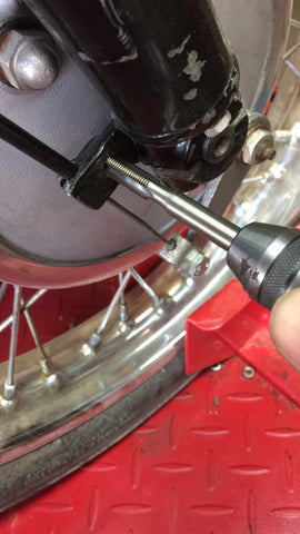
Using a 5/16" X 26 tap to chase the threads on the bottom fork legs. This threaded hole is designed to accept a bolt to attach the bottom front fender strap.
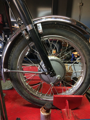
Front fender mounted into place with the correct fasteners. This photo consists of a NOS front fender, NOS bottom stays, NOS fork legs, NOS fork seal holders, reconditioned front hub with new liners and so much more.

Took the C15 out for a second test ride. I'm currently working on sorting the carburetor out as there seems to be a bug lingering within
This was the first ride with the silencer on and boy does it sure sound good!
I am very impressed with the handling and speed. It feels like a heavy weight machine but just miniature.
*NOS Smiths speedometer failed on me after 1 mile. Luckily I have another NOS speedo (100MPH) for this C15 and it works fine.

After observing my clear fuel line I noticed occasionally the fuel would have a brown colored appearance to it
I removed the side float boat cover to find a thick gooey like substance inside the float bowl. From there I immediately removed the entire carburetor to find this dark "gooey" like substance inside the inlet port.
The culprit of this problem was leftover residue from old gasoline that was left in the gas tank. When I cleaned the gas tank The first time I must have missed this residue inside the tank.
I completely stripped the carburetor and rebuilt it (this carb was new to begin with). Once the carb was cleaned I removed the fuel tank and began to clean the gas tank.
*Cleaning the gas tank I used Aceton along with a long thin chain inside to clean any debris or "goo" left inside the tank. Shaking the tank around with the chain works like a charm.
Jim Oldham
I have a 66 BSA silver star (259) that seems to run very well. I replaced the carburetor and the tank (the fiberglass original leaks terribly at the bottom rim where the floor was mated to the top.)
My issue is that the threaded rear valve inspection cover is stripped and falls off during an extended run. How does one deal with this matter ? Are new, used or reproduction threaded covers available ?
Nimesh
BSA c15 full engine rekvaid
Jon
Great write up and work! Would you kindly tell me what model Yuasa battery you ordered that fit so well? I couldn’t quite make out the numbers from the pictures.
Best Regards and safe riding,
Jon
Don Johnson
Great project! Aceton can dissolve/ruin old bike paint instantly. Kreem paint mask works quite well to protect the paint. Use a good 3 coats of mask! The mask dissolves instantly with water or sweat. It peels off easily also. Protect mask with Glad wrap, but keep wrap a ways away from filler cap so you don’t acetone between Glad wrap & mask. A large rubber plug works well to close filler neck during cleaning. Peel mask off or rinse with water. Water makes it gooey, but it comes off fine. Kreem paint mask is a good product. Kreem liner doesn’t hold up to California fuel well though. Caswell liner holds up very well though. Ethanol fuel can cause rusting, especially on upper inside of tank. Caswell will prevent that. Caswell does a very good job sealing pin holes from rust. I had a rust hole on upper surface & saved nice original paint & cured leak with Caswell liner. Instructions must be followed exactly!
Classic British Spares
@ Steve – no problem any time Steve! Thanks for reading today :)